Ensure reliability of your critical applications and minimize downtime with the T-APS Series. With the T-APS T-1 / E-1 automatic protection switches, you can quickly restore critical lines and equipment by easily switching over to redundant services.
T-APS – End to End Protection
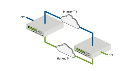
Protect your T-Span with a pair of automatic protection switches. Both links are continuously monitored and the switches coordinate switching, so you are never out of sync. Use a rack mounted, multi-switch system at the host location and standalone units at the customer premise or remote office.
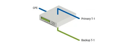
T-APS – Last Mile Redundancy
If you have redundant feeds to your facility these switches will insure you are always on the best option. Both feeds are monitored you set the parameters for automatic switching. Of course you always have control via network management.
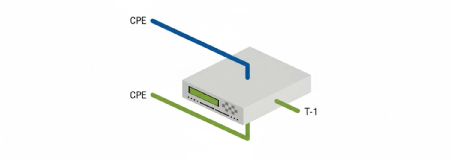
T-APS – REDUNDANT CPE EQUIPMENT
The T-APS series protects redundant equipment as well as redundant T-Spans. Back-up redundant routers, channel banks, or call center systems with these layer 1 reliable switches. Let Dataprobe application engineering show you how to integrate system reliability into any system.
Backup Switching On Autopilot
Simple Programming to Onsite Applicaitons
Multiple Circuit Switching Options
T-APS switches make redundancy switching easy. The T-APS continuously monitors T-1 or E-1 circuits and switches to the operational path, and provides automatic failover switching between redundant lines.
Designed for both line protection and equipment redundancy, the T-APS is ideal for any T-1 and E-1 networks where downtime is not an option. With the T-APS in control, you can have peace of mind that your critical applications will stay up and running.
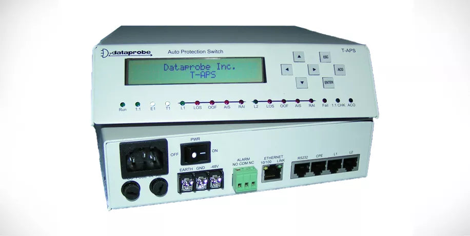
The T-APS is ideal for small offices and customer premise applications. It’s a self-contained, standalone unit capable of being powered by A/C or 48VDC sources, and line connections are standard RJ45 T1 and E1 (120 Ohm) connections. The T-APS features complete manageability via terminal or SNMP manager, plus status relay alarms.
With the T-APS, small offices can enjoy the same T-1 / E-1 circuit protection as larger enterprises.
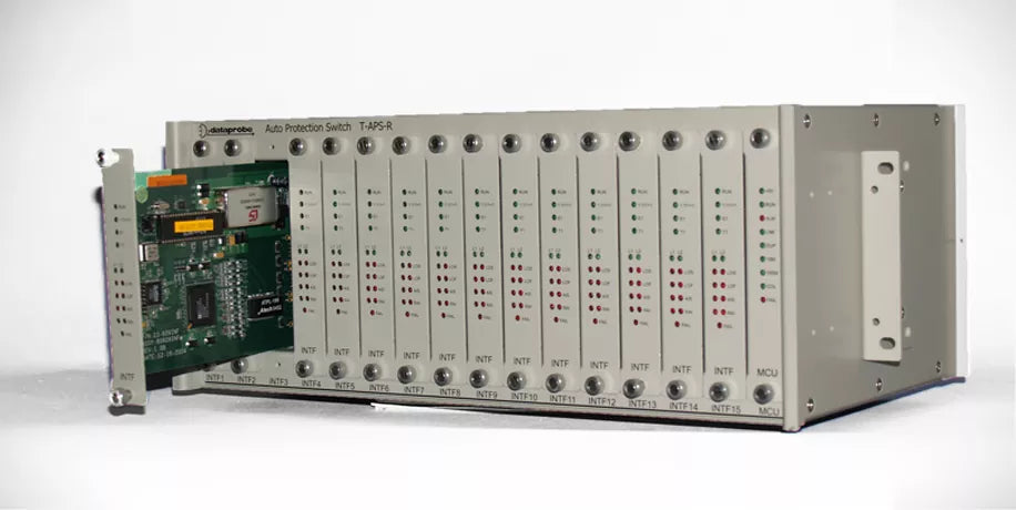
With the T-APS rack mount card and chassis system, you can provide T-1 / E-1 protection to multiple circuits. All of the features of the standalone T-APS are supported in the card version, but up to 15 primary/redundant circuits can be supported.
Each T-APS-R card provides a complete independent T-1 / E-1 protection switch, and all cards are managed from one network or serial interface with simple web pages and telnet menus.
The chassis supports either 48VDC or 120/240 VAC with external power supplies. T-1 / E-1 terminations are via RJ45 Modular Jacks.
ALL FEATURES
Features of T-APS Series Fully Automatic T-1/E-1 Protection Switching
SCREENSHOTS
Screenshots of T-APS Series Fully Automatic T-1/E-1 Protection Switching
T-APS Standalone Version
Ideal for Customer Premise Locations Redundant A/C and 48VDC Powered T-APS
T-APS-R Rack Mount Card
Complete T-1 / E-1 Protection Switch in 1 Card T-APS-R
T-APS Card Chassis
Holds up to 15 T-APS-R Cards 48 VDC Powered A/C Power Supply Optional T-APS-R-15
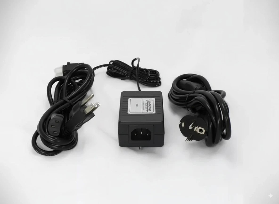
A/C Power Supply for Nest
A/C Power for Nest T-APS-R-15 Worldwide 110 – 250 VAC Up to 2 per T-APS-R-15 for Redundancy NOT Required for T-APS Standalone PS-48-WRI
SPECIFICATIONS
Specifications of T-APS Series Fully Automatic T-1/E-1 Protection Switching
-
T1 Interface
Line Code AMI B8ZS Frame Format SF ESF Unframed Bit Rate 1.544M b/s Impendance 100 Ohms Resistive Balanced Input Level 0-36 dB Output Level 6V p-p Line Build Out 0-655 feet -
E1 Interface
Bit Rate 2.048 M b/s Line Code AMI HDB3 Frame Format CCS CAS CCS+CRC CAS+CRC Unframed Impendance 120 Ohms Resistive Balanced Input Level 0-43 dB Output Level 6V p-p Line Build Out 0-655 feet -
LED Indicators
Run System Operational Master Master/Slave Configuration Status T1 System Configured for T1 E1 System Configured for E1 L1 Line 1 Selected / Operational L2 Line 2 Selected / Operational LOS Loss of Signal Indicator OOF Out of Frame Indicator AIS Alarm Indication Signal RAI Remote Alarm Indicator Failure System Failure Indicator LPBK Loopback Indicator ACO Alarm Acknowledgment Indicator -
Programmable Parameters Automatic Switching
Code Violation Fail: 1×10⁻³ to 1×10⁻⁷
Qualify: 1×10⁻⁵ to 1×10⁻⁹CRC Error Fail: 1×10⁻¹ to 1×10⁻⁵
Qualify: 1×10⁻³ to 1×10⁻⁷Frame Error Fail: 1×10⁻¹ to 1×10⁻⁵
Qualify: 1×10⁻³ to 1×10⁻⁷AIS Unframed or Framed Loss of Signal Fault Duration 500 ms, 1000 ms, 1500 ms, 2000 ms Recovery Qualify Time 0-98 Minutes, None